Picking the right Bending Part isn’t just about comparing prices, shapes, or delivery times — it’s usually a bit more complicated than that. You might look at a drawing and think everything’s spot-on, only to hit surprises during production. Small tweaks, like just a tiny change in material thickness, bend radius, or grain direction, can end up causing cracks, springback, or uneven edges that you definitely don’t want.
Dr. Taylan Altan, a well-known expert in metal forming at Ohio State University, often points out that it all boils down to this: “The success of forming depends on understanding the material, the tooling, and the process.” Honestly, that advice still rings true on the factory floor in the middle of a busy day. A good Bending Part isn’t just about size and shape — it starts with verified material data, the right tooling, and clear specs for dimensions. Plus, it’s crucial to have someone inspect that first sample carefully, instead of just giving the okay because it looks fine visually.
Details really do matter.
When evaluating a part, it’s smart to look at seven related areas. These include choosing the right material, setting the correct bend radius, tight tolerances, surface protection, expected production volume, equipment capabilities, and the supplier’s experience. Each of these factors can influence not just the cost, but also how well the part performs over time. For instance, a narrow flange might match the drawing, but it could leave too little room for stable tooling. Or a shiny surface might reveal marks that wouldn't show up on rough steel.
Now, let’s be real — this process isn’t foolproof. Even seasoned engineers can overlook tiny holes near bends or underestimate how much the material will spring back. That’s why trial runs, good measurement records, and honest feedback from suppliers are so important. The cheapest Bending Part isn’t always the best choice. Instead, go for the one that will perform reliably, help keep manufacturing efficient, and stay dependable once it’s installed. It’s all about the long game.
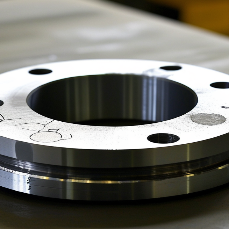
A bending part is a sheet-metal component shaped by controlled force along one or more lines. A press brake forms flanges, channels, brackets, covers, and frames without removing material. These parts appear in electrical cabinets, vehicle structures, appliances, agricultural equipment, and construction systems.
The World Steel Association reported 1.89 billion tonnes of crude steel production in 2023. This scale supports broad demand for formed Metal Components.
The IEA’s Global EV Outlook 2024 recorded nearly 14 million electric-car sales in 2023. That growth also increases demand for lightweight enclosures and structural parts.
Tip 1: Specify material, thickness, grain direction, and surface requirements.
Tip 2: Choose bend radii that suit the material, not only the drawing.
Tip 3: Check hole clearance near every bend.
Tip 4: Confirm tolerances with the fabricator before ordering an OEM Bending Part. A small mismatch can create visible gaps or assembly stress.
Tip 5: Request a flat-pattern review before production. Errors can multiply across several flanges.
Tip 6: Inspect the first article with calibrated angle and height gauges.
Tip 7: Test assembly using real fasteners, cables, or seals.
Springback may slightly change a 90-degree bend after release. It varies with alloy, tooling, and rolling direction.
A clean drawing is not proof of a good part. One hidden flange can block a screwdriver, cable path, or sealing surface.
A bending part should be selected by its job, not by its appearance. Define whether it will guide, support, clamp, absorb movement, or protect another component. Then record every load it may experience. Include tension, compression, bending, vibration, impact, and repeated cycles. A light bracket may carry 200 newtons today, but assembly errors can increase that force.
Operating conditions often change the design completely. Check temperature, moisture, chemicals, dust, and outdoor exposure. A part used near a heated enclosure may lose strength during long service. A part exposed to road spray may need better corrosion resistance. Specify the working temperature range and expected service life. Do not rely on an ideal workshop environment. Real equipment collects dirt.
Material thickness, bend radius, grain direction, and hole position affect performance. Sharp bends can create stress concentrations and visible cracks. Holes placed too close to a bend may distort during forming. I have seen a drawing pass visual inspection, then fail after repeated loading. The first calculation was too optimistic. Use hand calculations for early decisions, then confirm critical parts with testing or finite element analysis. Build a sample when tolerances are tight. Measure springback after forming, especially when the part must align with a mating surface. Record the actual load, temperature, and deformation during testing. A small measurement error can hide a serious weakness. Check fasteners and contact surfaces too; the bent part may be sound while its connection slips.
Choosing a bending material starts with the part’s working load, not its appearance. A stronger alloy is not always the safer choice. WorldAutoSteel’s Advanced High-Strength Steel Application Guidelines lists common AHSS grades from about 590 MPa to above 1,000 MPa tensile strength. These grades reduce thickness, but they also demand greater forming force and tighter springback control.
A thin, high-strength sheet may crack around a sharp corner. Low-carbon steel usually offers easier forming and more forgiving bends. Aluminum can reduce weight significantly. The International Aluminium Institute reports aluminum density near 2.7 g/cm³, compared with steel at about 7.85 g/cm³. However, aluminum alloys vary widely in ductility and temper. A soft temper may form smoothly, while a hardened temper can split near the outer bend zone.
For an ODM Bending Part, request the material grade, temper, minimum inside radius, and forming direction before production. Trial bending on the actual thickness is essential. I have seen drawings pass review, then fail when grain direction changed. That detail is easy to miss. Consider yield strength, elongation, coating behavior, and tool wear together. ASTM material data can guide selection, but real samples still reveal friction, springback, and edge quality. A perfect specification on paper may need adjustment on the press.
Tips 1–3: Start with the right shape. Open bends, generous flanges, and aligned features reduce forming stress. Avoid holes too close to a bend line. A practical rule is to keep the hole edge at least 1.5 times the material thickness away. Select the bend radius from the alloy, temper, and tooling, not appearance alone. A radius that is too tight can cause cracks or heavy springback. No chart replaces a first-off trial.
Tips 4–5: Treat wall thickness as a forming decision. Thin walls may distort near the bend, while thick walls need higher force and larger tooling. Keep thickness changes away from the bend zone when possible. World Steel Association data recorded 1,892.6 million tonnes of crude steel production in 2023. That scale hides major differences in grade and formability. Material certificates still matter. They are not paperwork decoration.
Tips 6–7: Check the inside radius, bend allowance, and final angle together. Use a sample part to compare the drawing with actual springback. Specify realistic tolerances, referencing ISO 2768 only when its limits fit the design. I often find that a perfect CAD model still needs one correction after forming. Leave room for that lesson. Record the trial radius, tool width, grain direction, and measured angle for production control.
| Tip | Design Dimension | Recommended Practice | Typical Data or Starting Range | Why It Matters |
|---|---|---|---|---|
| 1Choose a bend-friendly shape | Part geometry | Use straight flanges, consistent bend directions, and simple open profiles whenever possible. Avoid unnecessary formed features near a bend. | Prefer simple L-, U-, Z-, and channel-shaped profiles for standard press-brake work. | Simpler shapes reduce setup time, tool changes, distortion, and the risk of dimensional variation. |
| 2Set a practical inside bend radius | Inside bend radius R | Use the material thickness as the first reference, then adjust for alloy, temper, grain direction, and tooling. | Typical starting point: R ≈ 1.0t for mild steel; R ≈ 1.0–1.5t for stainless steel; R ≈ 1.5–2.0t for harder or less ductile materials. Here, t is sheet thickness. | A radius that is too small can cause cracking, excessive springback, tool marks, or inconsistent angles. |
| 3Maintain adequate wall thickness | Sheet or wall thickness t | Select thickness based on load, stiffness, corrosion allowance, and forming capability. Avoid abrupt thickness changes in one formed part. | Common sheet-metal ranges are approximately 0.5–6 mm; thicker sections may require specialized tooling or a different manufacturing process. | Very thin walls may dent or buckle, while thick walls increase forming force, bend radius, and springback. |
| 4Keep flanges long enough | Minimum flange length | Allow enough material to sit securely on the die. The required length depends on the die opening, material, thickness, and bend method. | For air bending, a practical first estimate is often about 0.7–1.0V, where V is the die opening; confirm with the selected tooling. | Short flanges can slip into the die opening, produce unstable angles, or become difficult to locate accurately. |
| 5Control bend-to-edge and bend-to-hole distances | Feature location | Keep holes, slots, notches, and cutouts away from the bend zone. If a feature must be close, use a relief or increase the setback. | A useful starting guideline is to place features at least 2t + R from the tangent line of the bend; increase the distance for large openings or soft materials. | Features placed too close to a bend can deform, elongate, close up, or pull the part out of square. |
| 6Account for bend allowance and springback | Flat pattern and final angle | Calculate the flat length using bend allowance or bend deduction, and validate the result with the actual material and tooling. | For air bending, the neutral-axis location is commonly estimated with a K-factor of about 0.30–0.50. Springback is generally higher in high-strength and stainless steels. | Ignoring material elongation and springback can cause incorrect flat patterns, open angles, and assembly problems. |
| 7Specify grain direction and tolerances | Material orientation and dimensional control | When cracking is a concern, bend across the rolling direction rather than parallel to it. Define only the tolerances required for fit and function. | For general press-brake work, a common angle tolerance starting point is approximately ±1°; tighter tolerances may require special tooling or secondary operations. | Grain orientation affects ductility, while unnecessarily tight tolerances increase cost, inspection time, and production risk. |
Design note: The values shown are practical starting guidelines for formed sheet-metal parts. Final limits should be confirmed with the material grade, temper, thickness, bend method, die opening, tooling condition, and required production tolerance.
Choosing a bending part starts with the manufacturing method, not the drawing alone. Check whether press braking, roll forming, or tube bending suits the geometry. Press braking handles short runs and varied angles well. Roll forming is better for long, repeated profiles. Tube bending needs careful control of wall thickness and ovality. Ask how the material will spring back after forming. I have seen a clean CAD model fail because its bend radius was too tight.
Tolerances should match the part’s function. Avoid specifying extremely narrow angle tolerances without a strong reason. They increase inspection time and scrap risk. Check material thickness, grain direction, and bend allowance together. A 90-degree bend may still vary by one degree across a long part. That difference can affect assembly. Define critical dimensions clearly, while allowing practical tolerance elsewhere. Over-tolerancing is a common mistake.
Surface requirements also influence the process. Protect visible faces from tool marks when appearance matters. Specify grain direction for brushed or directional finishes. Deburring should be discussed before production, especially around hand-contact edges. Small scratches may disappear after coating, but deep dents usually will not. Request sample parts when the finish is difficult to judge from words. My own reviews sometimes focus too much on shape and not enough on handling marks. A short production trial can expose that weakness before full release.
Choosing the Right Bending Part means checking more than its appearance. Quality standards should be clear before production begins.
Ask for material certificates, process controls, and documented acceptance criteria. ISO 9001-based procedures can indicate consistency, but certification alone does not prove every part is accurate.
For a Custom Bending Part, request a sample inspection report before approving the full order.
It should show bend angle, flange length, hole position, radius, and material thickness. Dimensional inspection may use calipers, height gauges, templates, or a coordinate measuring machine. Critical dimensions need defined tolerances. Otherwise, “acceptable” can mean different things to different people.
Testing should match the part’s real working conditions. A supplier may check springback, surface cracks, coating adhesion, and repeated-load performance. Ask how many samples were tested and whether results were recorded by trained inspectors.
Photos of a gauge reading help, but they are not enough. Traceability matters.
I learned this the hard way.
A clean bend can still hide internal stress or a small angle error. One missed measurement may cause assembly problems later. Review the inspection method, not only the final numbers.
If a supplier cannot explain the test sequence clearly, pause before choosing the part. A reliable partner welcomes questions and admits limits. That honesty is often more valuable than a perfect-looking report.
Choosing the right bending part requires more than comparing a single price. Supplier expertise should come first. Ask how they manage material thickness, bend radius, springback, and tolerance changes. A skilled team can explain its process clearly, not hide behind technical language. Request sample inspection reports and photographs of similar work. Small details matter.
Bending Part Quotes should show more than the unit cost. Check tooling fees, setup charges, packaging, shipping, and possible rework costs. A cheaper offer may become expensive after corrections. Compare equal specifications, materials, quantities, and inspection requirements. Ask whether the quoted price remains valid when production volumes change. I have seen unclear assumptions create avoidable disputes.
Lead time also needs careful checking. Confirm the schedule for design review, prototypes, production, and final inspection. Ask how delays are communicated and what happens when materials arrive late. Support matters after delivery. A responsive supplier should answer technical questions, provide traceable records, and help investigate dimensional problems. No supplier gets every forecast right. That is worth remembering. Choose a partner that admits risks early and offers practical adjustments, rather than promising perfect results without evidence.
Custom sheet metal parts are essential for a wide range of industrial control equipment, including control cabinets, electrical enclosures, operator panels, instrument housings, and protective covers. Using SGCC, aluminum, or SPCC, these components can be produced to meet different requirements for strength, weight, corrosion resistance, and appearance. Precision laser cutting supports accurate dimensions and clean edges, helping each part fit reliably within complex control systems and equipment structures.
To improve both functionality and presentation, the parts can be finished with spray painting and screen printing. Coatings help protect the metal surface while providing a professional appearance, and printed markings can identify switches, ports, warning areas, or operating instructions clearly. Customized designs and sizes are fully acceptable, allowing the sheet metal parts to match specific installation spaces and technical requirements.
A well-planned structure makes assembly, inspection, and future maintenance more convenient. Features such as mounting holes, access panels, fastening points, and ventilation openings can be integrated during the design stage. Whether used in compact control units or larger industrial equipment, customized sheet metal fabrication provides practical solutions for organized installation, dependable protection, and efficient servicing.
: Match the material’s strength, ductility, thickness, and bend radius. A stronger alloy is not always safer. Thin high-strength sheet may crack at sharp corners. Softer material usually forms more easily.
A tight radius stretches the outer bend surface. Cracks may appear near the corner. Use trial bends with the actual thickness. Paper specifications can mislead.
Confirm the material grade, temper, thickness, minimum inside radius, and forming direction. Check yield strength and elongation too. Grain direction can change the result.
Press braking suits short runs and varied angles. Roll forming suits long, repeated profiles. Tube bending requires wall-thickness and ovality control. The drawing alone is not enough.
Set narrow tolerances only for functional dimensions. Overly tight tolerances can increase inspection time and scrap. A long 90-degree bend may vary by one degree.
Identify visible faces, tool-mark limits, grain direction, and deburring needs. Protect edges that people may touch. Small scratches may disappear after coating. Deep dents usually remain.
Compare unit price, tooling, setup, packaging, shipping, inspection, and possible rework costs. Use equal materials, quantities, and specifications. A low price can become expensive later.
Request sample reports, photographs, prototype timing, and inspection records. Ask how the supplier handles springback and late materials. Good support includes traceable records and honest risk updates. Perfect forecasts are rare.
Choosing the right Bending Part begins with understanding its purpose, application, and working environment. Define the loads, operating temperature, exposure conditions, and expected service life before selecting a material. The material should provide the required strength, durability, corrosion resistance, and formability. At the same time, consider the part’s geometry, bend radius, wall thickness, and overall shape to prevent cracking, distortion, or unnecessary production difficulties.
A reliable selection also requires reviewing manufacturing methods, achievable tolerances, surface finish requirements, and inspection procedures. Quality standards and dimensional testing help confirm that every part performs consistently and fits correctly in its final assembly. Finally, compare suppliers based on technical expertise, production capacity, total cost, lead time, communication, and after-sales support. A well-qualified supplier can offer practical design advice, stable quality, and efficient production, helping you achieve a Bending Part that is functional, durable, manufacturable, and cost-effective.